
Direct answer: cookware polishing defects should be identified by how they change reflected light, where they appear, and whether they repeat around the part. Waves distort a straight reflection across a broad area. Burn marks create localized yellow, brown, blue, or dull zones associated with excessive heat. Drag lines are long directional scratches left by trapped particles or an incomplete abrasive sequence. Pits are discrete depressions that remain visible as the surrounding metal is polished. A useful defect atlas links each appearance to a likely process stage, a confirmation check, and a defined disposition.
Estimated reading time: 13 minutes.
This atlas is an inspection and troubleshooting tool, not a general catalog of decorative finishes. Buyers who first need to choose between mirror, satin, brushed, matte, hammered, or coated surfaces can review the separate guide to cookware surface treatment. The present guide starts after the target finish has been chosen and asks a narrower question: does the delivered surface match the approved standard, and if not, what process evidence should the factory examine?
What makes a polishing defect different from an intentional finish?
An intentional finish has a controlled texture, direction, gloss level, and boundary that repeat from unit to unit. A polishing defect interrupts that designed pattern. A brushed exterior may contain visible lines by design, but one deep line crossing the grain is a defect because its direction, depth, or reflectivity does not belong to the approved appearance. A mirror finish may reveal broad optical distortion even when no scratch can be felt.
Defect classification must begin with the approved finish specification rather than a universal idea of perfection. A light radial trace that is acceptable on the underside of an economy stockpot may be unacceptable on a premium mirror-polished sidewall. The same physical mark can therefore receive different commercial classifications based on surface zone, visibility, price position, and the signed reference sample.
What inspection conditions make the atlas repeatable?
A repeatable inspection uses the same light source, viewing distance, viewing angle, background, cleaning method, and observation time for every lot. Polished cookware acts like a curved mirror, so a small change in the room can create or hide an apparent defect. The inspection instruction should define the setup with photographs or a fixture instead of relying on the phrase good lighting.
Raking light is useful because light arriving at a shallow angle makes scratches, pits, and surface ripples easier to see. Diffuse frontal light is useful because it reveals overall gloss and color uniformity without producing one harsh highlight. The two conditions answer different questions, so a robust inspection uses both rather than choosing one as the only truth.
The cookware should be clean, dry, and at room temperature before inspection. Fingerprints, polishing compound, adhesive residue, protective oil, and water spots can imitate haze or staining. Cleaning must use an approved non-damaging method, because an inspector should not create new scratches while trying to confirm an existing mark.
The inspector should rotate the pan through a complete viewing cycle instead of judging one photograph. A true surface defect moves with the pan, while many reflected room features stay tied to the environment. Rotation also exposes handle shadows, curved shoulders, and the transition between sidewall and base, which are common places for a defect to hide.
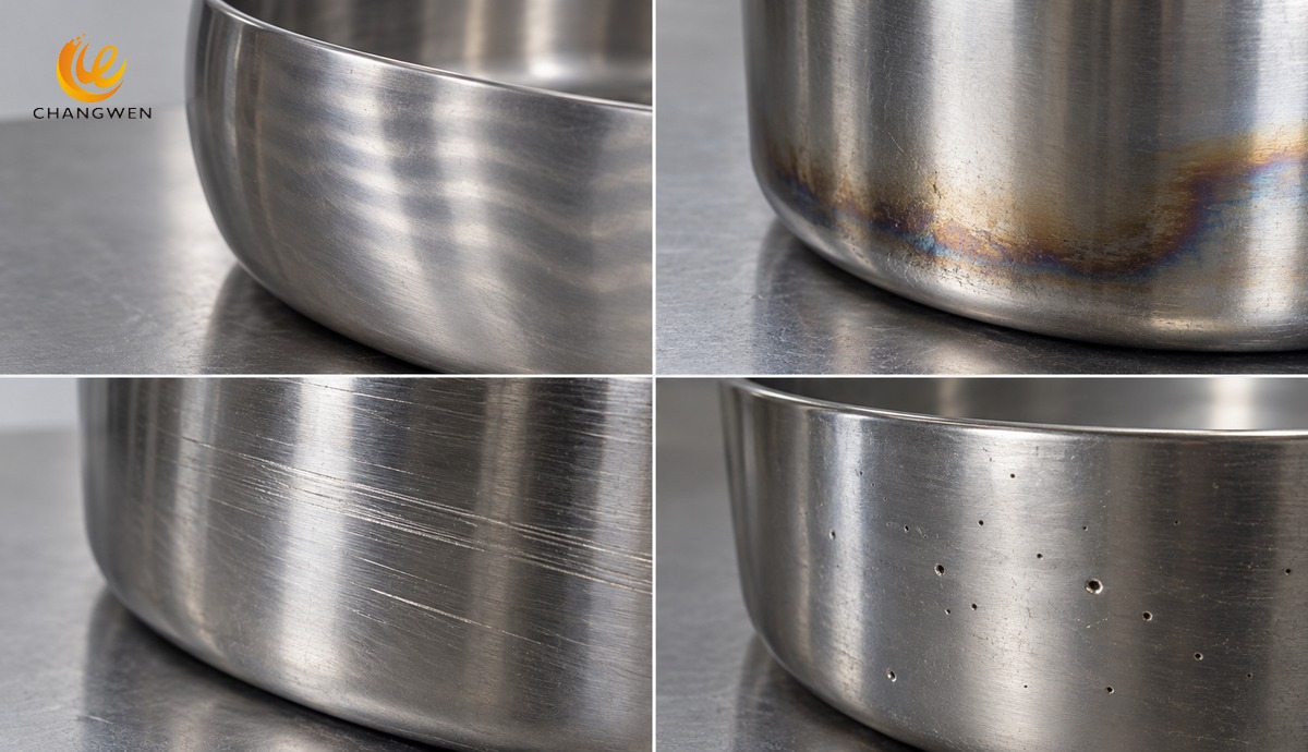
Cookware polishing defect atlas at a glance
| Defect | What the inspector sees | Likely process family | Best first confirmation |
|---|---|---|---|
| Waves | Broad bending or fluttering of reflected lines | Forming variation, uneven removal, local dwell, thin-wall distortion | Rotate under a straight reflected light bar |
| Burn marks | Localized color, darkening, or dull heat-affected patch | Excess pressure, speed, dwell, loaded abrasive, poor cooling | Clean the surface, then compare color and location |
| Drag lines | Long scratch trails that break the intended grain | Trapped coarse particle, debris, skipped grit, damaged belt | Check direction, depth, and repetition across consecutive parts |
| Pits | Isolated holes or crater-like depressions | Material inclusion, corrosion, forming damage, particle pullout | Inspect before and after light repolishing; review incoming material |
The likely process family is a starting hypothesis, not proof. The same visible symptom can have several causes. A wave may originate in the drawn shell and become obvious only after buffing. A pit may be created by corrosion, exposed by polishing, or confused with a piece of removable compound. Corrective action should follow a controlled confirmation rather than a visual guess.
What do polishing waves look like?
Polishing waves appear as broad, smooth distortion in a reflected straight line. The metal may feel smooth because the defect exists at a larger spatial scale than ordinary roughness. On a cylindrical wall, a light bar that should form a clean vertical reflection may bend, widen, narrow, or flutter as the pan rotates. The effect is often more obvious on mirror finishes than on satin finishes.
Waves differ from isolated dents because a dent has a localized center and a more abrupt change in shape. Waves differ from orange peel because orange peel creates a finer, distributed texture instead of one broad optical undulation. Waves also differ from normal curvature: designed curvature repeats symmetrically, while unwanted waves vary around the circumference or between units.
Uneven pressure and excessive dwell during manual polishing can remove more material from one zone and create a visible hollow. A worn or poorly supported wheel can follow the surface inconsistently. Forming strain, residual distortion, wall-thickness variation, or ridging in the starting sheet can also create a geometry that polishing merely makes more reflective. The root-cause review must therefore look upstream as well as at the polishing station.
A wave should not be corrected automatically by applying more polishing pressure. Additional removal can thin the wall, soften edges, enlarge the distorted area, and make the reflection worse. The safe decision is to compare dimensions and wall condition, test a controlled rework on a segregated sample, and stop if the geometry rather than the finish is driving the appearance.
What causes burn marks during cookware polishing?
A polishing burn is a localized area where frictional heat changed the oxide appearance or left the surface visibly dark, colored, or dull. Yellow, brown, blue, and gray tones can occur depending on temperature, time, surface condition, and material. A burn may follow the contact path of a wheel, cluster near a rim, or appear where an operator paused.
Burn marks differ from ordinary compound residue because residue can usually be removed by the approved cleaning step without changing the metal underneath. Burn marks differ from consumer cooking discoloration because factory burns are found before use and often align with a manufacturing contact pattern. The inspector should never classify color from an uncleaned part; oil and compound can shift the apparent hue.
Excessive contact pressure, excessive tool speed, long dwell, a loaded abrasive, insufficient compound, poor wheel condition, or inadequate cooling can all increase local heat. Austenitic stainless steel does not move heat away from a small contact zone as quickly as some other metals, so productivity settings that work on another material may create heat tint or distortion on cookware.
A burn is not only a color-matching question. Heat tint and embedded contamination can indicate that the expected surface condition was not restored after fabrication. Technical sources on stainless steel fabrication emphasize limiting heat and removing relevant contamination before final acceptance. The corrective plan may require controlled refinishing and cleaning or passivation steps appropriate to the product, not simply hiding the color with a finer buff.
How are drag lines identified?
Drag lines are elongated scratches or streaks created when a hard particle travels across the surface during grinding, polishing, handling, or cleaning. A drag line often has a consistent direction and may begin abruptly where a particle entered the contact zone. Several parallel lines can appear when debris remains trapped or when a damaged abrasive continues through multiple parts.
Drag lines differ from an intentional brushed grain because the designed grain is uniform in direction, density, and depth. A drag line is usually deeper, brighter, darker, wider, or misaligned. On a mirror surface, even a fine line can become prominent because the surrounding surface has little texture to disguise it.
The most common process hypotheses are coarse-particle carryover, incomplete cleaning between abrasive stages, a contaminated worktable, a damaged belt, or a grit sequence that advanced before earlier scratches were removed. Tools previously used on unsuitable materials can also introduce contamination. The investigation should examine consumables, cleaning discipline, storage, part contact points, and the exact moment when the line first appears.
A quick polish over the final line may round its edges without removing its deepest point. The line can then disappear under one light and return under raking light or after cleaning. Effective rework must return to a sufficiently early abrasive stage to remove the defect, then rebuild the specified finish through the complete sequence without skipping transitions.
What are pits, and why can polishing reveal them?
Pits are discrete depressions with a visible boundary, ranging from tiny pinholes to larger crater-like cavities. A pit remains attached to the same location as the cookware rotates and often casts a small shadow under raking light. Polishing residue trapped in the depression can make the pit appear dark even when the surrounding surface is bright.
A pit differs from a speck of dirt because cleaning removes dirt but not missing metal. A pit differs from a point impact because an impact may raise a lip or deform the surrounding geometry. A pit also differs from a rust-colored spot: discoloration describes color, while pitting describes loss of surface material. One location can show both, but they require separate observations.
Polishing does not necessarily create every pit that becomes visible after polishing. Mechanical finishing can expose nonmetallic inclusions, small cavities, forming damage, corrosion sites, or particle pullout that were less visible on a dull surface. Aggressive polishing can also enlarge a shallow discontinuity. The investigation should compare incoming sheet, formed but unfinished shells, intermediate stages, and finished units from the same batch.
Deep pits should not be blended away until the remaining thickness and intended use are considered. Removing surrounding metal to reach the bottom of a cavity can create a thin zone or visible dish. When pits repeat by coil, sheet location, or heat, material traceability and grade verification may be more useful than another adjustment at the buffing machine. The site guide to XRF testing for cookware explains what alloy screening can and cannot confirm.
How should buyers define visible surface zones?
A cookware drawing should divide the product into appearance zones based on normal use and retail presentation. Zone A commonly includes the principal exterior sidewall and any premium-facing surface. Zone B can include secondary visible areas such as the outer base transition. Zone C can include concealed or function-first locations, provided safety, cleanability, and fit are not compromised.
Zone definitions prevent one vague tolerance from being applied everywhere. A faint line on a concealed underside may have no effect on the customer, while the same line across a mirror sidewall can dominate shelf appearance. The zoning drawing must show boundaries clearly, because inspectors cannot classify a mark consistently if the border changes by interpretation.
Food-contact and hand-contact surfaces require separate consideration from decorative surfaces. A mark that is cosmetically minor may still be unacceptable if it creates a sharp edge, traps soil, exposes an unsuitable layer, or interferes with cleaning. Cosmetic classification must never override functional and safety requirements.
How do you build a controlled visual inspection station?
A controlled station needs a stable neutral background, defined diffuse light, a repeatable raking-light position, a clean turntable or marked rotation area, approved cleaning materials, and protected reference samples. The work instruction should specify where the inspector stands and how the product is rotated. A fixed setup reduces arguments caused by changing daylight or reflections from colored clothing.
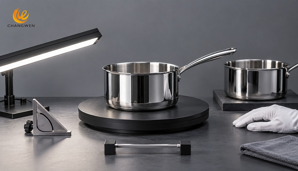
The inspection time should be long enough to cover all defined zones but short enough to represent normal production control. Unlimited searching with magnification will find features that customers never see, while a glance from several meters away can miss obvious shelf defects. The buyer and factory should agree on a practical viewing condition and record it in the quality plan.
Reference samples should include both the target finish and boundary defect panels when possible. A single perfect sample shows the goal but does not define the acceptance edge. A limit sample for a light drag line or mild wave tells inspectors what passes, while a reject sample shows the next level. Each sample needs an identifier, revision, approval date, and controlled storage.
How should polishing defects be classified for acceptance?
Defects should be classified by consequence, visibility, zone, frequency, and repair risk. A critical defect affects safety or legal compliance. A major defect substantially changes function, durability, cleanability, or the intended retail appearance. A minor defect departs from the reference but does not materially affect use and remains within an agreed visual limit.
The words critical, major, and minor are categories, not universal numeric limits. Each project must define defect examples, allowable counts, sample plan, and acceptance threshold. A buyer should not copy a quality table from another product without considering finish, price point, packaging, market expectation, and surface zone.
When is rework acceptable?
Rework is acceptable when the approved method removes the defect without violating thickness, geometry, finish direction, corrosion-control steps, cleanliness, marking, or dimensional limits. The reworked area must blend into the surrounding surface under the same inspection setup. A part is not conforming merely because the original mark became harder to see.
Waves caused by geometry and deep pits are often poor candidates for repeated polishing because repair removes additional metal. Shallow drag lines and localized haze may be more repairable when the correct abrasive sequence remains available. Burn marks require confirmation that color, oxide condition, contamination, and final cleaning have been addressed rather than visually masked.
Every recurring rework should trigger process review. Rework can rescue isolated parts, but using it as a normal production stage hides unstable tooling, consumables, training, or incoming material. The cost model should include labor, yield loss, delayed inspection, and the risk of inconsistent blending, not just the price of another buffing pass.
How do factories trace the root cause efficiently?
Efficient root-cause analysis starts by identifying the earliest process stage where the defect is present. Inspect incoming sheet, drawn shells, trimmed bodies, pre-polish surfaces, intermediate abrasive stages, final buffing, assembly, washing, and packaging. If the defect is absent before one step and present immediately after it, the investigation becomes much narrower.
Factories should preserve the affected part, adjacent parts, consumable batch, machine settings, operator, time, and material traceability. A single polished sample without production context rarely proves a cause. Consecutive samples show whether the defect is random, progressive, cyclical, tied to tool wear, or linked to a specific changeover.
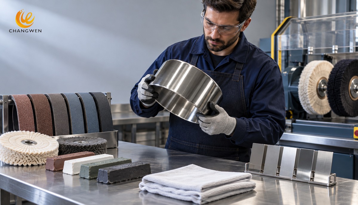
A controlled trial should change one factor at a time whenever practical. Replacing the belt, changing pressure, changing speed, adding compound, and switching the operator simultaneously may improve the part, but it will not reveal which variable mattered. A one-factor trial with before-and-after evidence creates a usable process lesson.
The corrective action must include containment, cause, correction, prevention, and verification. Containment identifies affected inventory. Correction handles current parts. Prevention changes the process. Verification proves the change works across enough production, not only on one carefully prepared sample. The Changwen overview of cookware quality control provides context for linking surface inspection to the wider production flow.
What should an OEM surface specification include?
An OEM surface specification should identify finish type, grain direction, target appearance, measurable parameters where useful, zone map, prohibited defects, conditional limits, inspection setup, cleaning state, reference samples, sampling plan, and rework rules. The specification should also state whether interior, exterior, base, rim, handle, lid, and logo zones use different criteria.
The purchase package should link the surface standard to the approved golden sample. The cookware golden sample checklist explains how visual approval fits with dimensions, construction, performance, packaging, and documentation. Surface appearance should never be signed off in isolation when later assembly can change the result.
Material grade and wall thickness should remain controlled because both can influence polishing behavior and rework risk. Buyers can use the stainless steel cookware thickness guide to frame structural choices, then define finish acceptance for the chosen construction. A visually successful trial on one gauge does not prove identical results on a thinner or differently formed shell.
Frequently asked questions
Does every burn mark mean the cookware is unsafe?
No. A visible burn mark is evidence of a process deviation that requires evaluation, not automatic proof of a safety failure. The factory must determine whether the issue is removable residue, heat tint, contamination, or another condition, then apply the approved technical and regulatory criteria for the product.
Should every visible drag line be rejected?
No universal rule applies. Acceptance depends on depth, length, contrast, surface zone, viewing condition, reference samples, and product positioning. A line that interrupts a premium exterior may be major, while a faint trace on a concealed noncritical zone may fall within an agreed limit.
Can polishing permanently fix deep pits?
Polishing can remove shallow surface discontinuities, but repairing a deep pit requires removing surrounding metal to the pit depth. That approach can reduce thickness and create a dish or wave. Deep or repeated pits should trigger material and upstream process investigation before rework.
How should buyers use this defect atlas?
Buyers should use the atlas to name the observed symptom, standardize photographs, choose a confirmation check, and request evidence from the earliest affected process stage. The atlas should not replace project-specific limit samples or engineering judgment. Its purpose is to make communication precise enough that buyer, factory, and inspector are solving the same problem.
Changwen supports stainless steel cookware development, manufacturing, OEM programs, and production quality control. Buyers preparing a new surface standard can review the Changwen R&D and manufacturing capabilities and provide finish references, zone drawings, inspection conditions, order quantities, and target market requirements through the contact page. A clear defect language at the quotation and sample stage is less costly than negotiating appearance after mass production.
-

6-Piece Stainless Steel Pot Set with Gold Handles CW-ES0610
-

Cookware wholesaler 12pcs pots and pans stainless steel cooking sets kitchenware tools and steamer CW-M1211
-

Premium Stainless Steel Frying Pan for Daily Cooking CW-TP010
-

China factory wholesale blue marble nonstick coating fry pan set stainless steel mirror polished frypans golden handles and knobs CW-M0303
-
6-Piece Matte Stainless Steel Pot Set with Multi-Color Handles CW-ES0617
-

Stainless Steel Stock Pot For Restaurants CW-SP002
-

China manufacturer stainless steel 12pcs cookware set non-stick frying pan blue glass lid golden handles & knobs CW-M1209N
-

Customized color box 4pcs stainless steel blue marble coating nonstick frypan set silicone cover wholesale kitchenware CW-M0401G